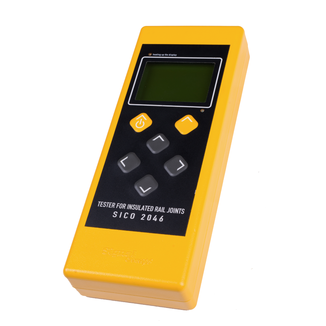
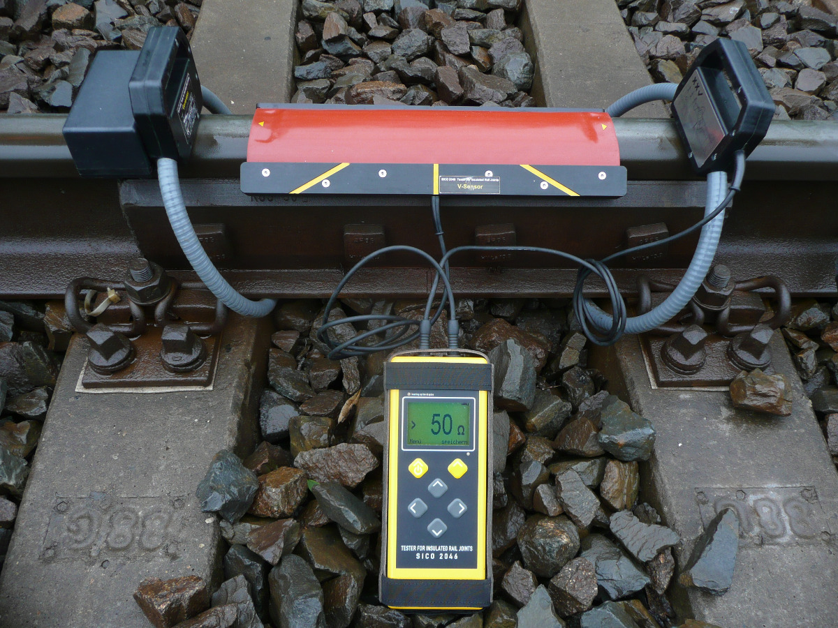
Tester for Insulated Rail Joints
SICO 2046
- Safe and contactless testing of insulated rail joints with direct resistance indication
- No more mistaken removal of faultless joints!
Application video:
For a first impression of its usage, please click here.
Data
Display: Graphic LC-display with background light
Resistance range: 0 ... 50 Ohm (with display >50 Ohm)
Operating temperature range: -20°C ... 55°C
Power supply:
- 2 accumulators Li-Ion, type PA-LH201.K01.R001 or
6 batteries / accumulators size AA
- batteries/accumulators removable
IP code: IP54
Dimensions: 420 x 320 x 160 mm
Weight (tester and case): 6 kg
Technology
- In most cases, track circuits of individual track sections are isolated by insulation joints. A precise detection of insulated rail joint bridges is indispensable to ensure safe operation without failure.
- Classic methods of measuring insulated joints are based on dipolar measurements. Measurement follows Ohm’s law, but only the voltage measured over the joint is reliable. Current measurement is realized via a shunt in the tester. This way, currents through the insulated joint and, additionally all parallel current paths close to the insulating joint are measured. Parallel current paths can be caused by faulty insulations of connecting rods and metal parts, as well as by intended connections via impedance bond transformers. That may lead to the display of a resistance being too low and a faulty insulated rail joint.
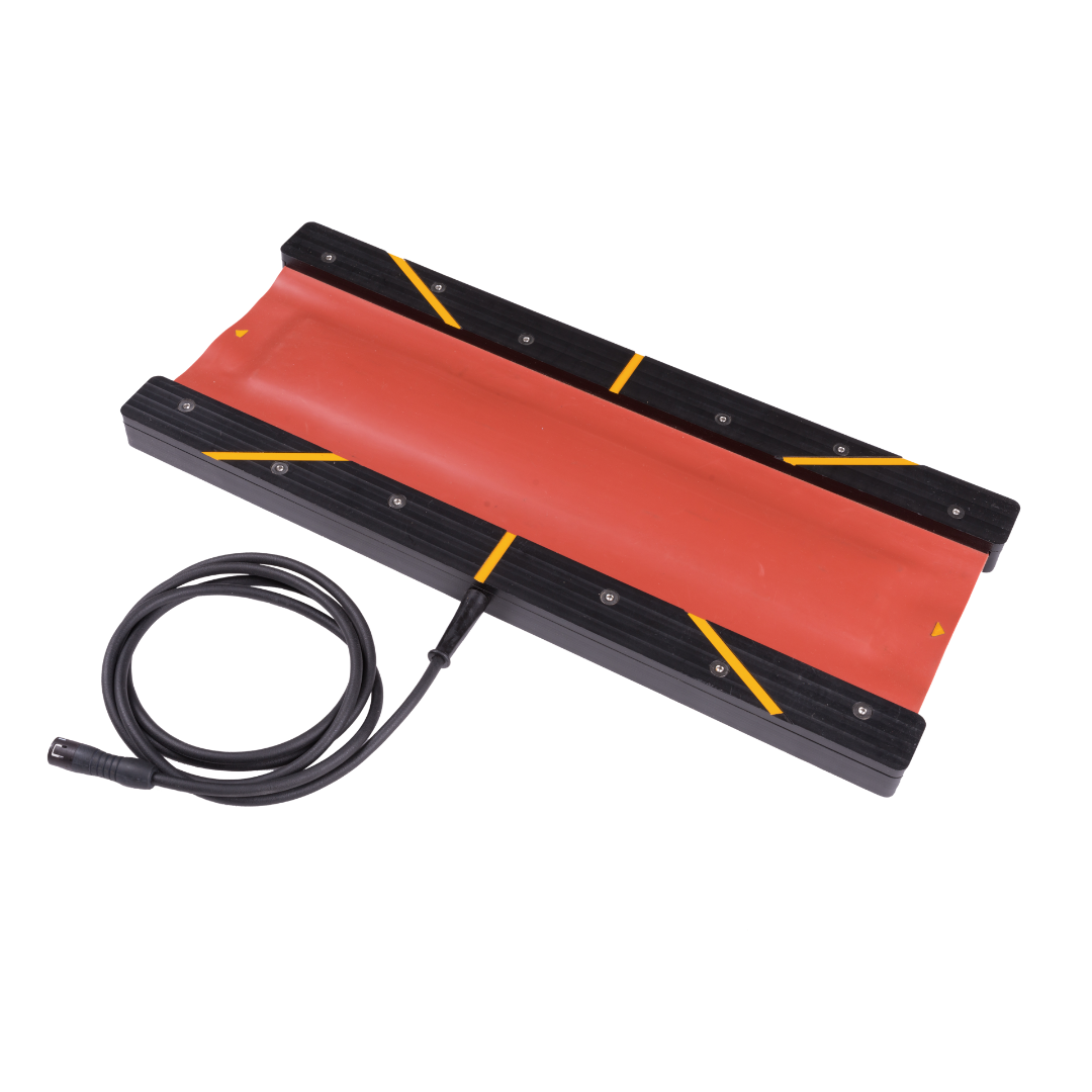
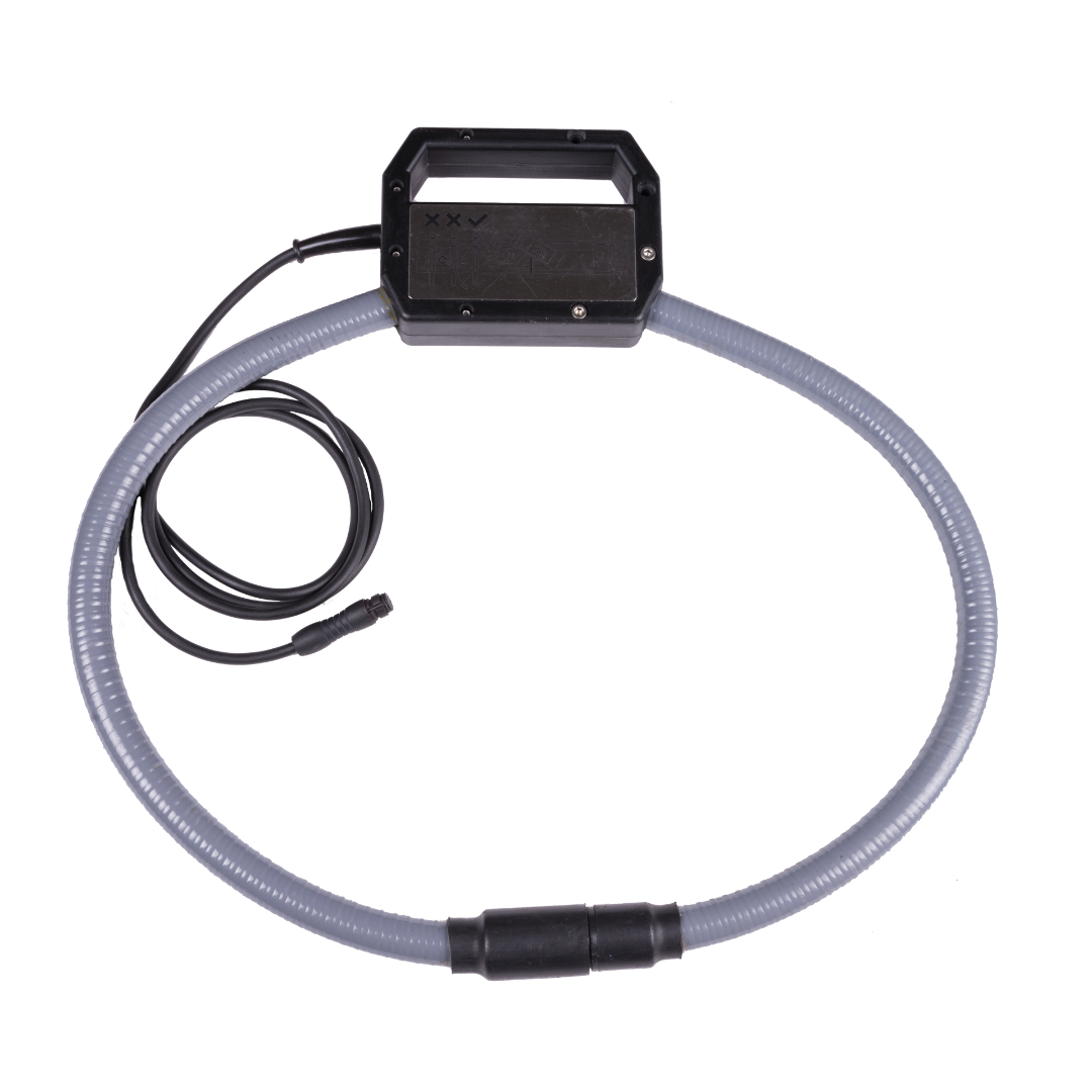
- The Insulated Rail Joint Tester SICO 2046 offers an innovative solution providing true resistance measurements from insulated rail joints. Current measurement is taken via a separate current transducer (left picture: part on the right side; bound around the insulated joint) and not, as common in most devices via an internal shunt. Just the current through the insulated joint is measured. Parallel current paths close to the insulated joint won't distort the current measurement. The tester separates the current flow from external portions, e.g. current from the impedance bond, connecting line or bedding, and distinguishes between the actual resistance of the joint and parallel loads. In addition to the contactless voltage measurement, the resistance of only the insulated joint is measured. This means no more mistaken removal of faultless joints.
- Measurements are taken contactless. A current transducer measures the current (left picture: part on the right side). Voltage is taken via insulated contacts on the tester's bottom.
- A transmitter bound around the rail sends a signal.
- The test results are stored in the device.
Delivery
- Tester
- V-Sensor
- C-Sensor
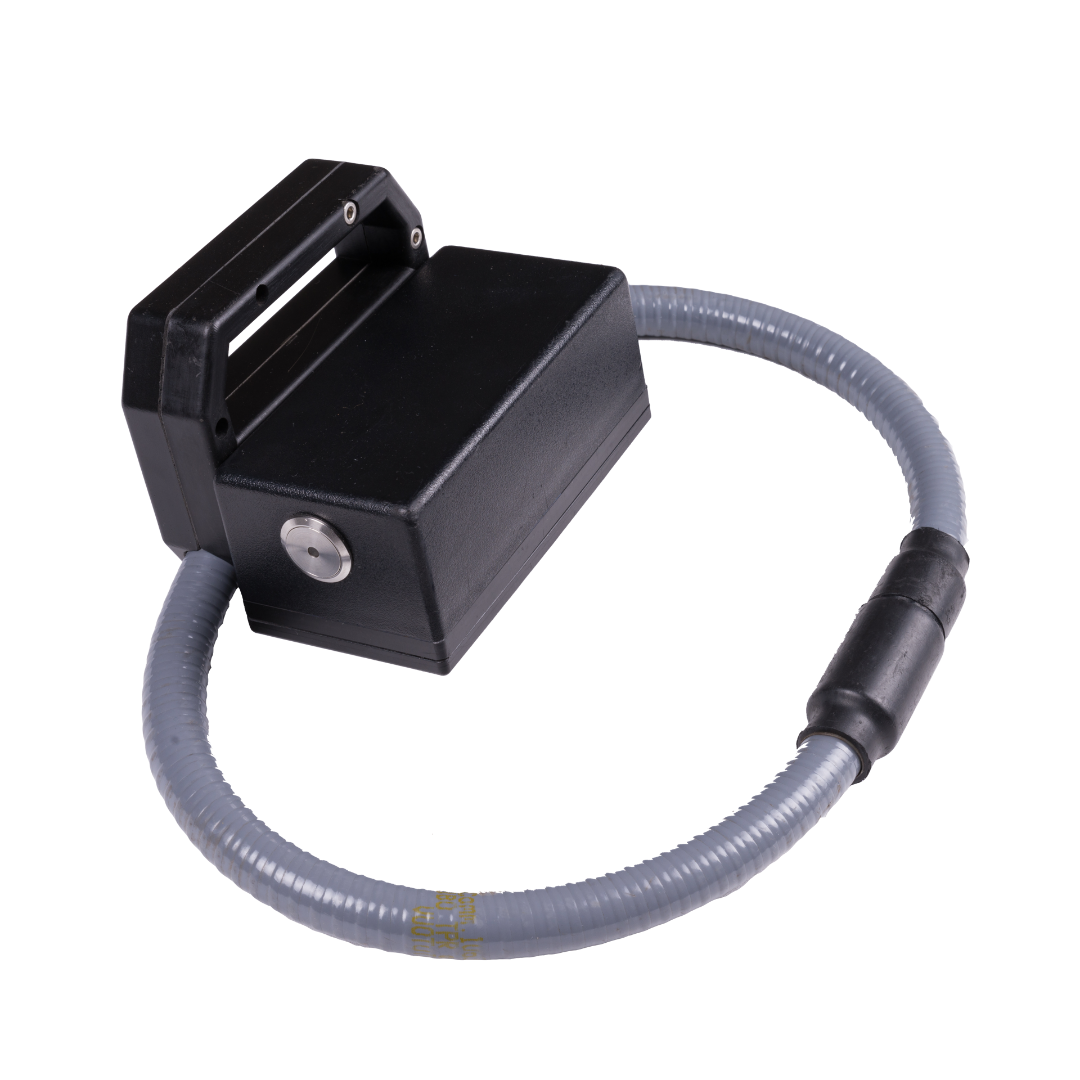
- Generator
- Test resistor 33 Ohm with test probes
- 2 Lithium-Ion accumulators type PA-LH201.K01.R001
- Charger for Lithium-Ion Cells type PA-LH201.K01.R001 SICO 5007 with manual
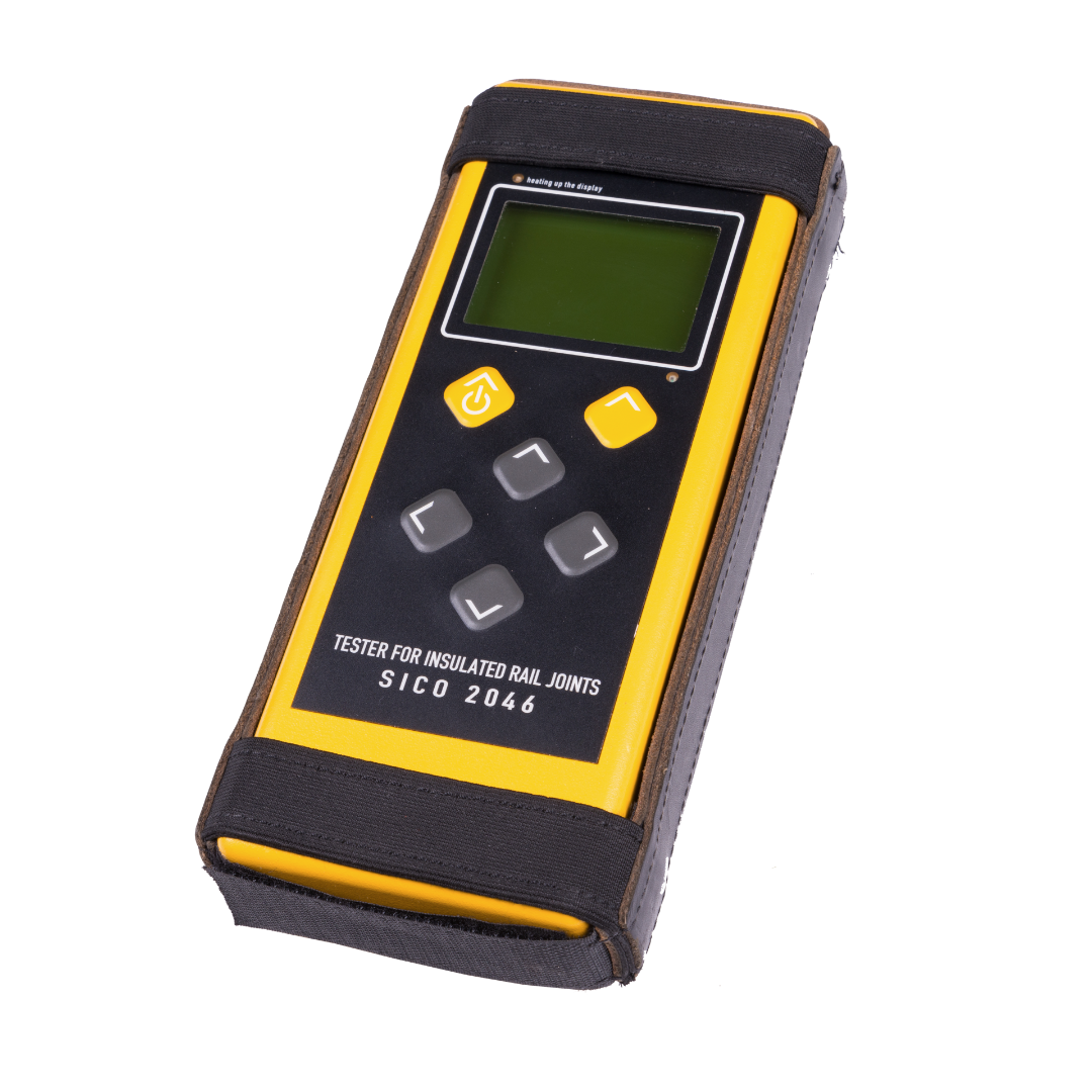
- Protector for tester
- Transport case
- Manual
- Acceptance test certificate 3.1 according BS EN 10204
product documents
Profil
Signal Concept GmbH
Since its founding in 1993 Signal Concept GmbH has specialised in measuring and testing instruments for railway signalling and safety systems. In the meantime we deliver our products to many clients on the national and foreign markets.
Signal Concept unites product developing, producing, adjusting, and selling at...
